What Is a PLC Splitter and How Does It Work in an FTTH Network?
A PLC splitter is a passive optical component that divides the light from one feeder fiber into several output fibers. In an FTTH network, it allows one OLT port to share the optical distribution network with multiple ONTs or ONUs—without electrical power at the splitting point.
The splitter does not route customers, assign bandwidth or amplify the signal. It simply divides optical power. The OLT, ONTs and PON protocol manage the actual communication.
Where the PLC splitter sits in an FTTH network
A basic FTTH path looks like this:
OLT → feeder fiber → PLC splitter → distribution/drop fibers → ONTs
For downstream traffic, the optical signal leaves the OLT and reaches the splitter. Each output branch receives a share of that signal. For upstream traffic, signals from the ONTs return through the same passive device and are combined toward the feeder fiber. The PON system coordinates when each ONT transmits.
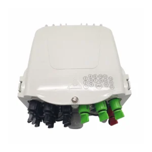
The splitter may be installed in a central office, street cabinet, fiber distribution hub, closure, distribution box or terminal box. Its package must match the available space and the way technicians will splice, connect and maintain the network.
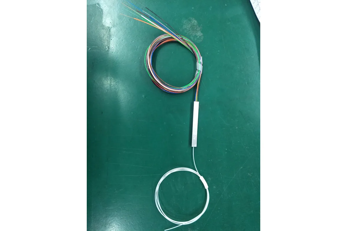
How a PLC splitter divides light
PLC means Planar Lightwave Circuit. Inside the device, an optical waveguide circuit is formed on a small chip. Light entering the input waveguide passes through a branching network and is divided across the output waveguides. Fiber arrays connect the chip to the input and output fibers.
For an equal 1×8 splitter, one input becomes eight outputs with broadly similar power. The chip does not create extra optical power, so every increase in split ratio adds unavoidable loss.
| Split ratio | Output fibers | Ideal division loss* |
|---|---|---|
| 1×2 | 2 | 3.0 dB |
| 1×4 | 4 | 6.0 dB |
| 1×8 | 8 | 9.0 dB |
| 1×16 | 16 | 12.0 dB |
| 1×32 | 32 | 15.1 dB |
| 1×64 | 64 | 18.1 dB |
*These are theoretical power-division values. Actual insertion loss is higher because the complete component also has excess loss, connectors or splices and manufacturing tolerances. Use the supplier’s tested specification when calculating the link budget.
Why the split ratio affects the whole network
A larger split ratio lets one OLT port reach more subscribers, but it leaves less optical-power margin for fiber attenuation, connectors, splices and repairs. This is why the split ratio should be chosen together with the complete optical budget—not from subscriber count alone.
The splitter can be installed in one stage, such as 1×32, or cascaded across two stages, such as 1×4 followed by 1×8. A centralized design is often easier to monitor, while a cascaded design may place capacity closer to users. The correct choice depends on route length, cabinet locations, take-up rate, maintenance access and the supported PON class.
For a practical calculation workflow, see our GPON and XGS-PON optical power budget guide.
PLC splitter production is more than connecting fibers
After the PLC chip and fiber arrays are assembled, the splitter still needs suitable fiber routing, protective packaging and—when ordered—connector termination. Connector endfaces must be processed and inspected, while completed channels should be tested against the agreed optical limits.
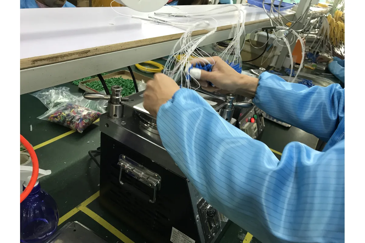
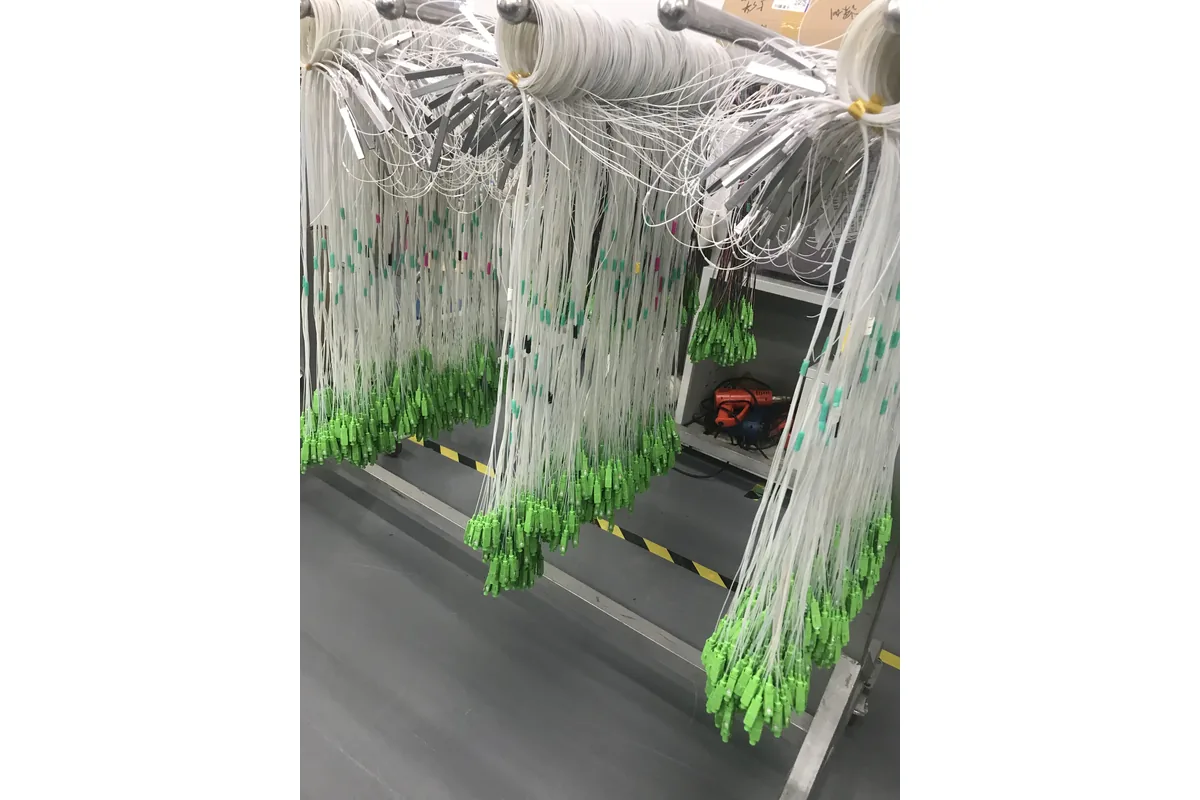
For purchasing, ask what test data will be supplied and whether results are recorded by channel or by batch. Do not accept “low loss” as a complete specification.
What should a buyer specify?
- Split ratio: 1×2, 1×4, 1×8, 1×16, 1×32, 1×64 or another design.
- Network topology: one-stage or cascaded splitting and the planned location of each splitter.
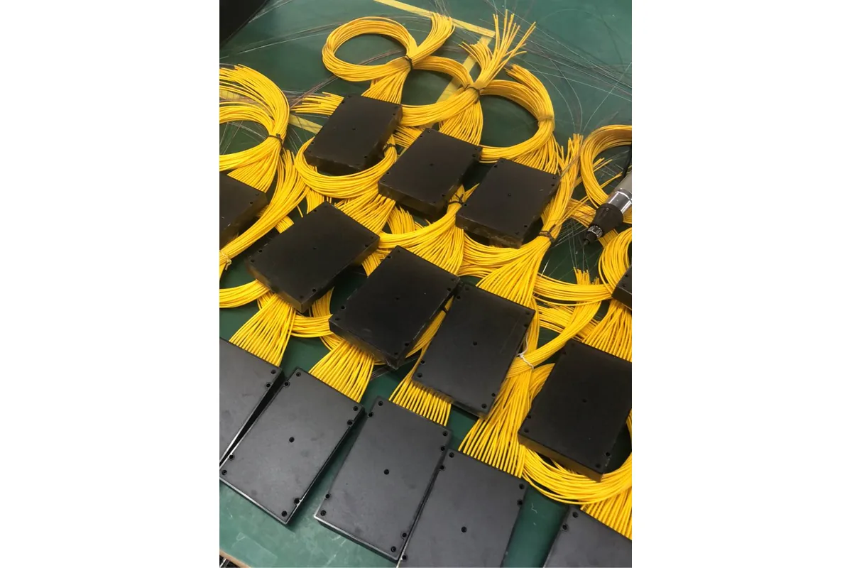
- Package: bare fiber, blockless, ABS box, LGX cassette, rack mount or another enclosure format.
- Connector and polish: for example, SC/APC or SC/UPC, or unconnectorized tails for splicing.
- Fiber and tail details: fiber type, buffer size and input/output length.
- Optical requirements: maximum insertion loss, channel uniformity, return loss and other project limits.
- Documentation: test report, labels, serial numbers, packaging and inspection requirements.
- Commercial information: quantity, destination and required delivery schedule.
Package names are not interchangeable. Our PLC splitter package guide explains bare fiber, blockless, ABS, LGX and rack-mount options separately.
A practical ordering example
“1×8 PLC splitter” is not enough for production. A clearer RFQ might say:
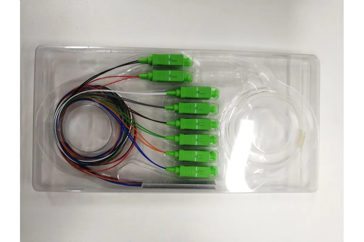
1×8 PLC splitter, blockless steel-tube package, SC/APC connectors, specified input and output tail lengths, project insertion-loss limit, individual test report, required quantity and delivery country.
The exact values should follow the network design. If you need a compact reference product, review the NetLast 1×8 SC/APC mini PLC splitter and send your required configuration for confirmation.
Quick questions
Does a PLC splitter need power?
No. It is a passive optical component and does not need a local electrical supply. The OLT and ONTs are active devices, but the optical distribution path between them can remain passive.
Does a PLC splitter reduce internet speed?
The splitter divides optical power, not a fixed electrical bandwidth. User capacity and service speed depend on the PON system, OLT configuration, subscriber load and service plan. The splitter must still fit the optical-power budget.
Can the same PLC splitter work with GPON and XGS-PON?
A splitter is wavelength-passive, but compatibility must be checked against the exact operating wavelength range, loss specification, connector configuration and coexistence design required by the project.
Need a PLC splitter quotation for an FTTH project?
Send NetLast your split ratio, topology, package, connector polish, fiber-tail length, optical limits, quantity and delivery country. We can review the configuration and related passive components before quotation.
Sources
- ITU-T G.807: Generic functional architecture of the optical media layer
- NetLast: Fiber Optic PLC Splitter 1×8 SC/APC Mini Splitter
Related FTTH hardware guide: A PLC splitter must be matched to the terminal topology and port plan. See how to choose a pre-connectorized fiber access terminal box before finalizing the distribution-point BOM.
Need to compare splitter technologies? Read our PLC splitter vs FBT splitter selection guide before confirming the split pattern, wavelength plan and test limits.