Both PLC and FBT splitters divide optical power without requiring electricity, but they are built differently and suit different network designs. A PLC splitter is usually the stronger option for equal splitting across multiple outputs, broad wavelength plans and repeatable high-density FTTH deployment. An FBT splitter remains useful when a project needs a low output count or a defined unequal split, such as a monitoring or tap branch.
Neither technology should be approved from the name or unit price alone. Compare the required split pattern, output count, operating wavelengths, maximum loss by port, uniformity, package, connectors, environmental qualification and complete installed cost.
PLC splitter vs FBT splitter: quick comparison
| Selection point | PLC splitter | FBT splitter |
|---|---|---|
| Full name | Planar Lightwave Circuit splitter | Fused Biconical Taper splitter or coupler |
| Optical structure | Waveguide circuit on a planar substrate connected to input and output fibers | Two or more fibers fused and tapered so optical power couples between them |
| Common split pattern | Usually equal 1×N or 2×N distribution | Equal or unequal low-count coupling, depending on the design |
| Scaling to more outputs | Well suited to compact multi-output assemblies | More outputs may require multiple fused stages or a different architecture |
| Wavelength planning | Broadband PLC products are commonly available | Performance is tied closely to the specified wavelength window |
| Port-to-port consistency | Commonly selected when equal-output uniformity is important | Unequal outputs may be intentional and must be checked by designed percentage |
| Typical decision driver | Standardized FTTH/PON distribution and higher equal split counts | Low-count branch, asymmetric tap or a defined coupling requirement |
| What still varies | Loss, uniformity, package, fiber, connector, qualification and test limits | Loss at each output, wavelength window, package, fiber, connector, qualification and test limits |
These are technology tendencies, not universal specifications. A qualified FBT device can be the correct choice for one design, while a poorly specified PLC assembly can still fail the project requirements.
What is a PLC splitter?
PLC stands for Planar Lightwave Circuit. Light enters an optical waveguide chip and is divided through a branching circuit before the outputs are aligned to an array of fibers. The device does not amplify the signal; every split consumes part of the optical power budget.
PLC technology is widely used for equal distribution in FTTH and other passive optical networks. Corning’s current PLC splitter specification, for example, lists applications across FTTH network architectures and highlights insertion loss and uniformity as key characteristics. The exact wavelength range, loss and environmental limits remain product-specific and must come from the approved datasheet.
If the reader first needs the network role and basic operating principle, see What Is a PLC Splitter and How Does It Work in an FTTH Network?
What is an FBT splitter?
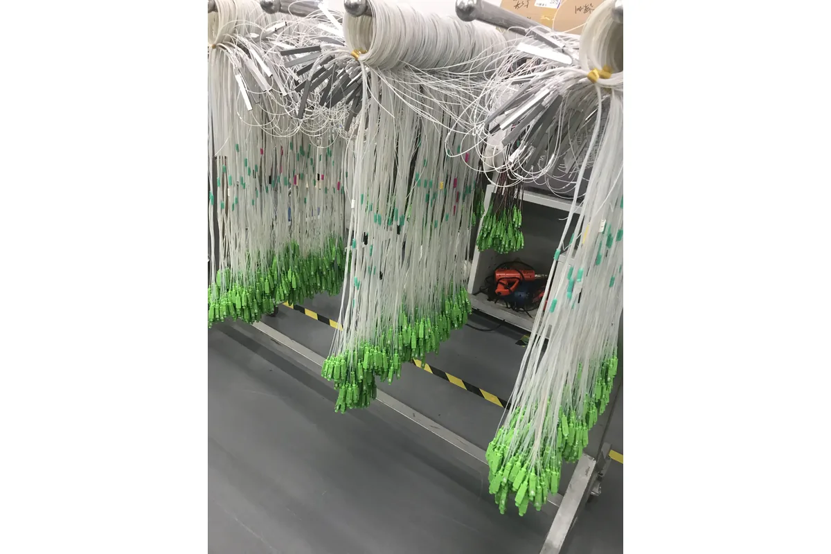
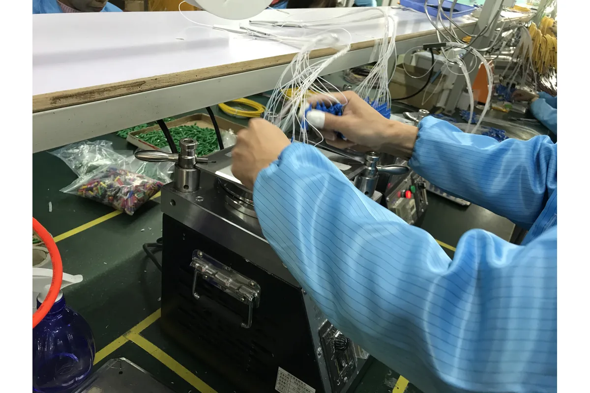
FBT stands for Fused Biconical Taper. The manufacturing process heats, fuses and stretches optical fibers while monitoring how power transfers between the output paths. Changing the coupling region allows the finished device to produce a defined power distribution.
This makes FBT technology useful when a design needs a low-count coupler or an unequal split. A branch can intentionally receive a smaller share of the optical power while the main route retains a larger share. That is different from a standard equal-output distribution requirement.
Current manufacturer portfolios illustrate the distinction without creating a universal rule. CommScope’s bare splitter and coupler guide lists PLC configurations across 1:N and 2:N arrangements, while its FBT products are offered in low-count configurations that include asymmetric ratios. Another supplier’s range may differ, so the project must verify the exact orderable device.
Difference 1: equal distribution or unequal coupling?
Start with the required power distribution, not the number printed on the housing.
For a residential FTTH distribution point where each output should follow the same nominal loss class, an equal PLC splitter is normally the easier architecture to specify and repeat across many locations.
For a route that must pass most optical power forward while diverting a smaller portion to a branch or monitoring point, an asymmetric FBT coupler may fit the topology more directly. In that case, “uniformity” between the two ports is not the goal—the outputs are deliberately different.
The drawing should identify which output is the primary path, which is the secondary path and the intended percentage at each port. Labels and test reports must use the same port definition.
Difference 2: output count and network scalability
PLC splitters are commonly selected when one input must serve many equal outputs. Their planar structure supports standardized multi-output configurations without building the assembly from a long chain of individual low-count couplers.
FBT technology is strongest when the required coupling function is simple and low count. Cascading multiple FBT stages can create more outputs, but it also creates additional component interfaces, cumulative tolerances, routing work and test points. That does not automatically make the design unacceptable; it means the complete cascade must be evaluated rather than treating it like a single equal splitter.
Do not choose the largest split ratio only to maximize subscriber count. The OLT class, route attenuation, connectors, splices, restoration margin and future topology all belong in the optical budget. Our GPON and XGS-PON optical power budget guide explains that calculation workflow.
Difference 3: operating wavelength plan
“Works at 1310 nm” is not a complete splitter specification. A PON may use several downstream, upstream, coexistence, monitoring or video wavelengths, and the passive component must meet its loss and uniformity requirements across the project-defined windows.
Broadband PLC products are commonly available for access networks. FBT products may also cover one or more useful windows, but their coupling behavior is closely tied to the designed wavelength range. Buyers should therefore compare the actual wavelength table on both datasheets rather than repeating the oversimplified claim that every FBT splitter works at only one wavelength.
If future coexistence or migration is part of the plan, include those wavelengths in the RFQ now. A splitter selected only for today’s service can become an avoidable constraint later.
Difference 4: insertion loss, uniformity and testing
Never compare a typical PLC loss value with the maximum loss of an FBT assembly—or a bare component with a connectorized product. Use the same basis for both quotations:
- maximum insertion loss at every specified wavelength;
- uniformity between equal outputs, when applicable;
- loss of the primary and secondary outputs for an unequal FBT device;
- return loss, directivity and polarization-dependent loss where the project requires them;
- connector and splice contribution;
- test method, reference method and measurement direction;
- individual-channel report or batch report;
- applicable qualification and acceptance documents.
The Fiber Optic Association notes that a splitter, coupler or combiner is a passive device and describes component testing as a loss-measurement task comparable in principle to testing other fiber assemblies. The important procurement point is traceability: the report must identify the actual port, wavelength and acceptance limit.
Difference 5: package type and installation location
PLC or FBT describes the optical technology, not the complete field-ready product. Either device still needs packaging and fiber management appropriate to its installation.
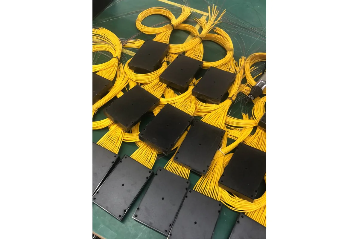
For a PLC splitter, common commercial formats include bare fiber, blockless steel tube, ABS box, LGX cassette, tray and rack-mount assemblies. The correct format depends on the closure, distribution box, cabinet, ODF or equipment rack. Review the options in our PLC splitter package types guide.
An FBT device can also be supplied as a protected component or integrated into a tray or enclosure. The installer must confirm fiber-tail protection, bend management, fixing method, connector access and sealing. Neither PLC nor FBT technology alone proves that a product is suitable for direct outdoor exposure.
Difference 6: purchase price versus installed system cost
FBT can be economical for a simple low-count or asymmetric design. PLC can deliver better project economics when many equal outputs must be standardized in a compact assembly. These are cost tendencies, not quotations.
Compare the installed system rather than only the passive component:
- number of splitter or coupler stages;
- splice and connector count;
- tray, closure or cabinet capacity;
- installation and labeling time;
- optical testing by channel;
- replacement-stock strategy;
- documentation and traceability;
- quantity, packaging, destination and delivery schedule.
A lower unit price can disappear if the design needs several devices, extra splicing or more enclosure space. Conversely, a project should not pay for a high-output PLC architecture when a controlled two-port tap is all that is required.
When should you choose PLC or FBT?
Choose a PLC splitter when the project calls for:
- standardized equal distribution;
- multiple subscriber outputs;
- broad multi-wavelength access-network planning;
- controlled port-to-port uniformity;
- compact integration into a repeatable FTTH BOM.
Evaluate an FBT splitter or coupler when the project calls for:
- a low output count;
- a defined asymmetric split;
- a monitoring or tap branch;
- a wavelength window and coupling ratio documented by the exact device;
- a simple architecture where the complete tested assembly is commercially suitable.
If either list conflicts with the approved network drawing or loss budget, the drawing and verified specifications take priority.
RFQ checklist for PLC and FBT splitters
Send the supplier enough information to produce like-for-like quotations:
- splitter technology, or permission to propose PLC/FBT against the topology;
- 1×N or 2×N input/output configuration;
- equal or unequal split, with exact percentage by labeled port;
- operating wavelengths and loss limits at each window;
- package type and installation location;
- input/output fiber type, buffer or cable construction and length;
- connector type and APC/UPC polish, or splice-ready tails;
- environmental and qualification requirements;
- individual or batch test-report format;
- labels, serial numbers, packing and accessories;
- quantity, destination country and requested delivery schedule.
NetLast’s current 1×8 SC/APC mini PLC splitter is one example of a compact PLC product. Confirm the current datasheet and project-specific configuration before treating it as suitable for another network.
Need help comparing a splitter BOM?
Send NetLast the topology, equal or unequal split pattern, operating wavelengths, optical limits, package, connector and fiber-tail requirements, quantity and destination. We can review the missing information and prepare a project-specific PLC splitter quotation or related passive-component BOM.
FAQs
Is a PLC splitter always better than an FBT splitter?
No. PLC is usually preferred for equal multi-output FTTH distribution, while FBT can be the better fit for a low-count or asymmetric coupling requirement. The correct device is the one that meets the topology, wavelength, loss, packaging and qualification requirements.
Can an FBT splitter provide an unequal split ratio?
Yes, unequal optical coupling is one of the important reasons FBT devices are used. The RFQ and test report must define which physical port receives each percentage and the maximum loss allowed on both paths.
Can a PLC splitter be used for GPON and XGS-PON?
Potentially, but compatibility must be confirmed from the exact operating wavelength range, loss limits, connector configuration and coexistence design. “PLC” by itself is not proof of compatibility with every PON system.
Which splitter has lower insertion loss?
There is no reliable answer without a specific split pattern and like-for-like datasheets. Compare the maximum loss of the complete assemblies at the same wavelengths, including connector or splice contributions. Unequal FBT outputs will intentionally have different losses.
Are splitter and coupler the same term?
Both terms can describe passive components that divide or combine optical power. In purchasing practice, “splitter” is common for equal multi-output distribution, while “coupler” is often used for low-count or unequal devices. The optical drawing is more reliable than the name alone.
What information affects a fiber splitter quotation?
Key inputs include split configuration, equal or unequal ratio, wavelength range, loss limits, package, fiber tails, connectors, qualification, test-report format, quantity, packing and delivery destination.