How to Calculate a GPON and XGS-PON Optical Power Budget
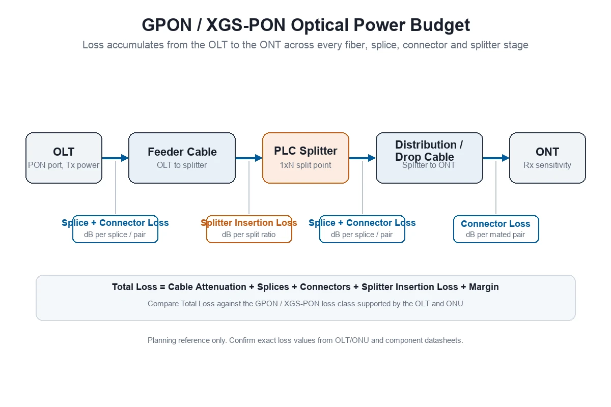
FTTH project teams often ask a supplier to “just confirm the splitter and cable will work” without sending any loss numbers. That request is hard to answer responsibly, because GPON and XGS-PON systems only operate within a defined optical power budget: the gap between the OLT transmit power and the minimum receiver sensitivity at the ONT, minus every loss point in between.
If a passive optical distribution network (ODN) design exceeds that budget, ONTs may register intermittently, lose signal in bad weather, or fail completely at the far end of a split. This guide walks through how to estimate a GPON/XGS-PON power budget before you send an RFQ, so the PLC splitter, fiber cable, connector and patch cord order matches what your OLT/ONU pairing can actually support.
The method below uses general PON industry references. It is a planning tool, not a substitute for your OLT/ONU vendor’s link-budget calculator or your fiber and splitter suppliers’ datasheets.
Quick reference: GPON vs XGS-PON loss classes
PON standards define optical power budget in “classes,” each covering a minimum-to-maximum loss range between the OLT and the ONT. The table below summarizes the commonly referenced classes; always confirm the exact class supported by your specific OLT and ONU hardware.
| PON type | Standard | Common loss classes | Typical nominal range |
|---|---|---|---|
| GPON | ITU-T G.984.2 | B+, C+, C++ | roughly 13-32 dB depending on class |
| XGS-PON | ITU-T G.9807.1 | N1, N2, E1, E2 | roughly 14-35 dB depending on class |
A higher class letter generally allows more loss budget, which supports longer reach, a higher split ratio, or more margin for aging and repairs. But higher-class optics are not automatically installed on every OLT port, so this should be confirmed with your equipment vendor before the ODN is finalized, not after installation.
What optical power budget means for FTTH projects
Optical power budget is the maximum allowable loss between the OLT transmit port and the ONT receiver, while still meeting the minimum receiver sensitivity with an acceptable margin.
In practical terms, it answers one procurement question: how much cable length, how many splices, how many connectors and what splitter ratio can this PON link support before the signal becomes too weak or too strong?
This matters for buyers because the ODN bill of materials is not just “cable plus splitter.” Every fiber optic cable run, every splice, every patch cord connector and every PLC splitter stage consumes part of the same fixed budget. If the design consumes too much, the network will not perform reliably even if every individual component is correct on its own.
Inputs needed before calculation
Before estimating a power budget, gather the following project inputs. Do not guess these values; if they are unknown, mark them “to be confirmed” in the RFQ rather than assuming a number.
- OLT optical transmit power range (from the OLT/SFP vendor datasheet)
- ONT/ONU minimum receiver sensitivity (from the ONT vendor datasheet)
- PON class supported by the OLT and ONU (for example GPON C+ or XGS-PON N2)
- Feeder cable route length (OLT to splitter location)
- Distribution/drop cable route length (splitter to ONT)
- Planned split ratio, and whether splitting happens in one stage or two stages
- Number of connector pairs in the path (patch cords, pigtails, adapters)
- Number of fusion splices in the path
- Required safety margin for aging, repairs and temperature variation
If any of these inputs come from a project drawing or BOM, send that document together with the RFQ. It is far easier for a supplier to check whether a splitter and cable combination fits the design when the actual route and connection points are visible.
Typical loss elements: fiber, splice, connector, PLC splitter, margin
A GPON/XGS-PON power budget calculation adds up loss from five general categories. The figures below are commonly referenced industry ranges for planning purposes; the exact insertion loss, attenuation and connector-loss values for any NetLast product should be confirmed from the current datasheet before being used in a final design.
Fiber attenuation
Single-mode fiber attenuation is normally estimated per kilometer, and it varies by wavelength. Commonly referenced planning ranges are:
- Around 0.35 dB/km at 1310 nm
- Around 0.21-0.25 dB/km at 1490/1550 nm
Fusion splice loss
A well-executed fusion splice is commonly planned at around 0.1 dB per splice for estimating purposes. Poor splicing, contamination or fiber mismatch can increase this significantly, which is one reason test documentation matters.
Connector loss
A connector pair (for example, a patch cord mated to an adapter) is commonly planned at around 0.3 dB per mated pair for estimating purposes. A project with many patch points, such as a distribution box with multiple connectorized interfaces, can accumulate more connector loss than expected if this is not tracked.
PLC splitter insertion loss
PLC splitter insertion loss increases with split ratio because the optical power is divided among more output ports. Commonly referenced theoretical/typical planning values include:
| Split ratio | Typical planning insertion loss |
|---|---|
| 1×2 | around 3.6 dB |
| 1×4 | around 7.2 dB |
| 1×8 | around 10.5 dB |
| 1×16 | around 13.5 dB |
| 1×32 | around 17.5 dB |
| 1×64 | around 21.0 dB |
These are general planning figures, not a guarantee for any specific NetLast splitter batch. Actual insertion loss, uniformity and wavelength-dependent loss should be confirmed from the product datasheet or test report before the value is used in a final design.
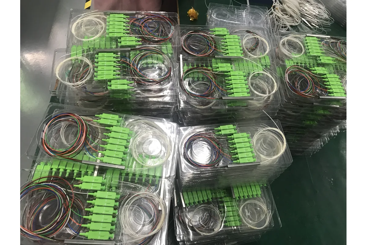
The production view above shows connectorized PLC splitters grouped in trays during order preparation. For buyers, this type of image is useful for confirming the requested connector style, pigtail arrangement and batch handling before shipment, but it should still be supported by the agreed datasheet and batch-specific test records.
Safety margin
Most FTTH designs reserve a margin for aging, future repairs, temperature effects and manufacturing tolerance. Reserving too little margin is a common cause of links that pass initial testing but degrade over time.
Example calculation structure (without inventing project specs)
The general structure for estimating total loss is:
Total estimated loss =
  (feeder cable length x fiber attenuation per km)
  + (distribution/drop cable length x fiber attenuation per km)
  + (number of splices x splice loss)
  + (number of connector pairs x connector loss)
  + PLC splitter insertion loss (for the selected ratio)
  + reserved safety margin
This total is then compared against the loss class supported by the OLT/ONU pairing. If the total is below the maximum loss of the assigned class, the design has margin. If it is close to or above the maximum, the project should reconsider split ratio, route length, connector count, or PON class before ordering the ODN bill of materials.
Because exact NetLast product loss values require datasheet confirmation, this article does not publish a worked numeric example using NetLast-branded figures. For a project-specific calculation, send the inputs above to NetLast so the passive ODN BOM can be checked against your OLT/ONU vendor’s link-budget tool.
How splitter ratio and two-stage splitting affect margin
Split ratio has the largest single effect on power budget in most FTTH designs, because insertion loss increases sharply as the ratio grows.
Two common splitting approaches are:
- Single-stage splitting: one splitter, for example 1×32 or 1×64, located centrally.
- Two-stage splitting: a smaller splitter near the OLT (for example 1×4 or 1×8), followed by a second splitter closer to the subscriber (for example 1×8 or 1×16).
Two-stage designs can offer more flexible deployment, since the second-stage splitter can be added closer to actual subscriber uptake rather than installed all at once. However, two-stage designs typically add an extra set of connector interfaces and sometimes a longer combined cable path, both of which consume additional budget. When comparing single-stage and two-stage options, buyers should ask their supplier to check the combined splitter insertion loss, connector count and route length for each option, not just the final split ratio.
RFQ checklist for the passive ODN BOM
To get an accurate quotation and a design check, include the following in your RFQ:
| RFQ field | What to specify |
|---|---|
| PON type and class | GPON or XGS-PON, plus the loss class supported by the OLT/ONU |
| OLT/ONT budget data | Transmit power range and minimum receiver sensitivity, if available |
| Feeder cable length | Distance from OLT/ODF to splitter location |
| Distribution/drop cable length | Distance from splitter to ONT/subscriber |
| Split ratio and stages | Single-stage or two-stage, with ratio at each stage |
| Splitter package type | Bare fiber, blockless/mini, ABS box, LGX cassette or rack mount |
| Connector requirements | Connector type, polish (APC/UPC), and expected number of mated pairs |
| Splice count | Expected number of fusion splices along the route |
| Terminal-box layout | Port count, splice tray space and installation environment |
| Required margin | Aging, repair and temperature margin expected by the project |
| Testing documents | OTDR results, insertion-loss test reports or other required records |
If you already have a project drawing, BOM or OLT/ONU vendor link-budget printout, send it together with the RFQ. It is easier for a supplier to check the splitter and cable selection when the actual route, split points and connection count are visible.
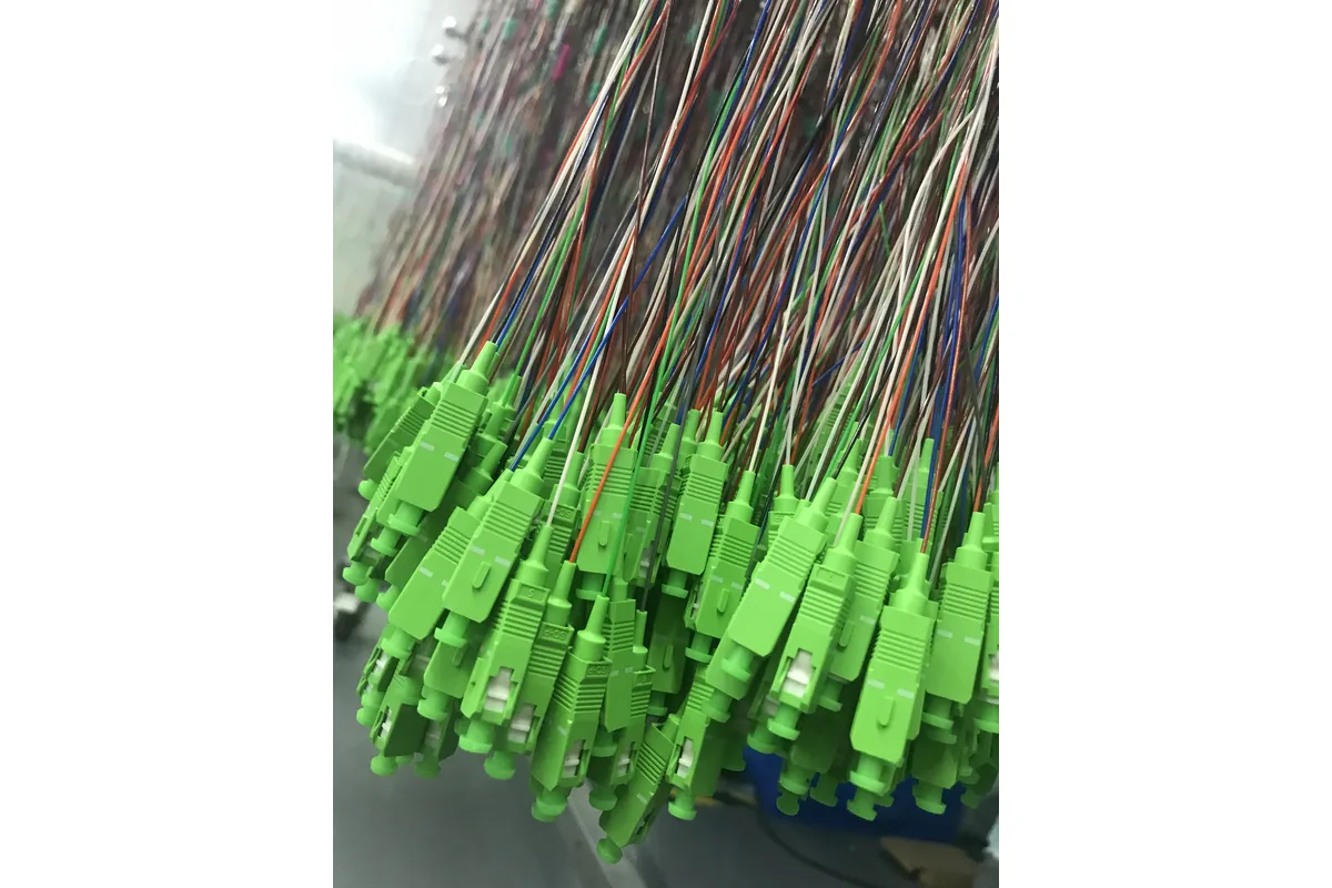
For larger or customized orders, buyers can also request production photos, connector and pigtail identification, label samples, packaging details and the proposed test-report format before shipment. A real workshop view is most useful when it is paired with traceable inspection records rather than treated as a standalone marketing claim.
Common mistakes in FTTH power budget planning
Choosing split ratio before checking the loss class
A 1×64 split ratio may be attractive for cost efficiency, but it may not fit every PON class or route length. Confirm the OLT/ONU loss class first, then evaluate split ratio against it.
Ignoring connector count in distribution boxes
Every patch point in a distribution box or patch panel adds connector loss. A design with many connectorized interfaces can lose more budget than a simpler spliced design, even at the same split ratio.
Reserving no margin for aging and repairs
A link that barely meets the budget on day one may fail after a repair splice, a re-terminated connector, or normal aging. Always reserve margin rather than designing to the theoretical maximum.
Mixing loss assumptions from different sources
Using fiber attenuation figures from one source, splitter loss from another, and no margin at all can produce a budget estimate that looks fine on paper but does not match field conditions. Keep assumptions consistent and documented.
Treating the calculation as final without vendor confirmation
This guide provides a planning method. The final design should be confirmed against the OLT/ONU vendor’s official link-budget tool and the actual datasheets of the fiber cable, splitter, connectors and patch cords selected for the project.
How NetLast can support your ODN design
NetLast supplies fiber-optic passive network products for FTTH deployment, including PLC splitters, fiber optic cable, fiber optic patch cords and fiber optic distribution boxes.
For a project-specific power budget check, send NetLast your route length, planned split ratio (single-stage or two-stage), connector type, terminal-box layout and target PON class. NetLast can help review whether the selected splitter, cable and connector combination fits within the loss class supported by your OLT/ONU equipment before quotation.
FAQs
What is optical power budget in FTTH?
Optical power budget is the maximum allowable optical loss between the OLT transmit port and the ONT receiver, based on the transmit power and the ONT’s minimum receiver sensitivity, while keeping the loss within the PON standard’s defined class.
How much loss does a PLC splitter add?
PLC splitter insertion loss depends on the split ratio: it increases as more output ports share the same optical power. Typical planning ranges run from around 3.6 dB for a 1×2 splitter up to around 21 dB for a 1×64 splitter, but the exact figure should be confirmed from the product datasheet.
How much safety margin should buyers reserve?
The appropriate margin depends on the project, expected aging, and how many future repairs or reconfigurations are anticipated. Rather than designing to the theoretical maximum loss, most FTTH projects reserve a margin and confirm the target with their OLT/ONU vendor or network engineering team.
Is the method different for GPON and XGS-PON?
The overall calculation structure is the same: transmit power minus receiver sensitivity minus total loss, compared against the standard’s loss class. GPON and XGS-PON define different loss classes under ITU-T G.984.2 and G.9807.1, so the class supported by your specific OLT and ONU hardware should be confirmed for each PON type separately.
Need a power-budget check before requesting a quotation?
Send NetLast your OLT and ONT models, feeder and drop lengths, split ratio and stages, connector polish, splitter package type, terminal-box or ODF layout, delivery country and required test documents. We can review the passive ODN configuration against the loss-class information you provide and help organize a matching FTTH bill of materials for quotation.
The splitter technology also affects the component specification. Use our PLC vs FBT splitter guide together with the optical power budget before approving the BOM.