ADSS Fiber Optic Cable vs Figure 8 Cable: How to Choose
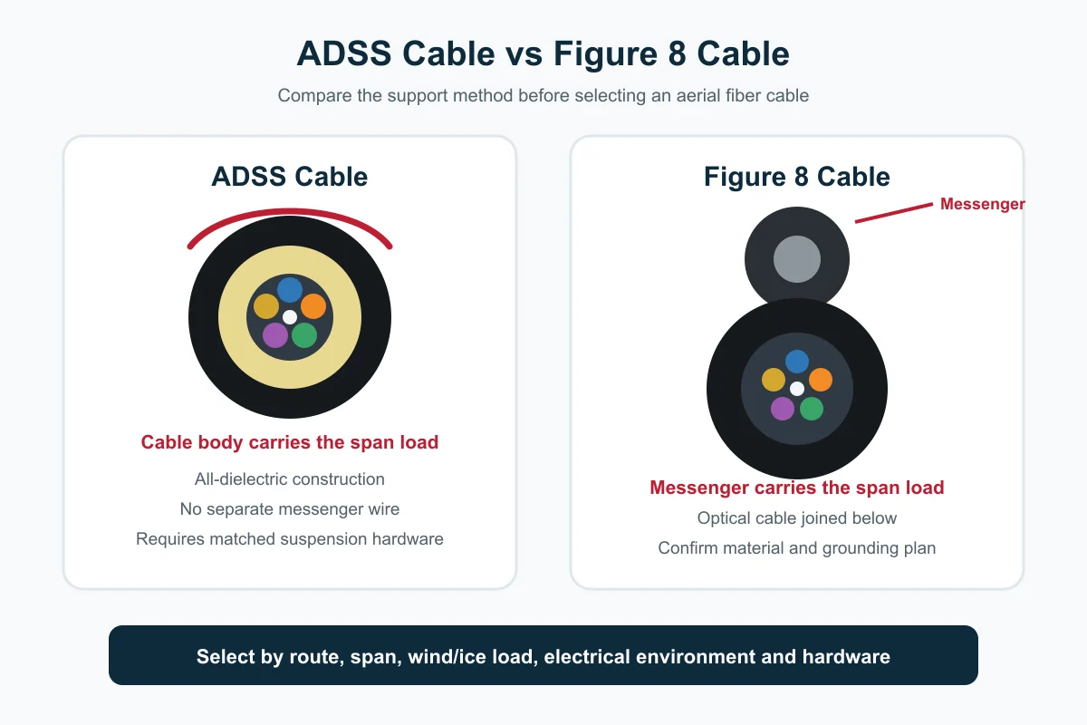
ADSS cable and Figure 8 cable are both used for aerial fiber networks, but they support the span in different ways. ADSS is an all-dielectric, self-supporting cable: the cable body and its non-metallic strength elements carry the mechanical load. Figure 8 cable places the optical cable beside or below a separate messenger, creating the familiar “8” profile; in many common designs, the messenger is metallic and carries the span load.
The right choice is not simply “ADSS for long spans” or “Figure 8 for low price.” Buyers should compare the actual route, pole ownership, electrical environment, span, wind and ice load, sag, installation hardware, grounding requirements, maintenance method and total installed cost.
This guide helps ISPs, contractors, distributors and project buyers prepare a technically useful aerial-cable RFQ without inventing specifications.
If your route follows power-line infrastructure and the choice is between a communication-only cable and an optical ground wire, compare ADSS vs OPGW cable before finalizing the system.
Quick answer: when should you choose each cable?
Choose ADSS cable when the route requires an all-dielectric aerial design, a separate messenger is not desired, or the cable will share utility-pole infrastructure where the owner requires an approved non-metallic solution. The exact ADSS design must still be selected from a sag-and-tension calculation and the electrical environment.
Choose Figure 8 cable when a messenger-supported structure fits the route, the pole owner permits it, installers are familiar with messenger clamps, and the project accepts the grounding/bonding plan required by a metallic messenger. Figure 8 can be practical for telecom poles, rural routes, campuses and access networks, but the permitted span depends on the exact product.
ADSS vs Figure 8 cable comparison table
| Selection point | ADSS cable | Figure 8 cable |
|---|---|---|
| Mechanical support | Cable body is self-supporting | Separate messenger carries most span load |
| Metallic element | All-dielectric design | Messenger is often steel; confirm the exact construction |
| Cross-section | Usually round | Messenger and optical cable form a figure-8 profile |
| Electrical planning | No conductive messenger, but utility clearance and electrical-field review still matter | Metallic messenger requires grounding/bonding and clearance planning |
| Installation hardware | ADSS dead-ends, suspension units and armor rods sized to cable/load | Messenger clamps, suspension/dead-end hardware and grounding accessories as applicable |
| Pole-space impact | One round cable body | Messenger and cable profile may use more vertical/attachment space |
| Span selection | Model-specific sag-and-tension design | Model-specific messenger and cable-load design |
| Mid-span access | Depends on cable construction and closure plan | Messenger can support cable while optical section is accessed, depending on design |
| Price comparison | Cable may cost more, but total installed cost depends on hardware and labor | Cable may look economical, but include grounding, hardware and pole work |
| Best RFQ starting point | Route, span, NESC/local load case, electrical environment and hardware | Route, span, messenger material, grounding plan and hardware |
No row in this table replaces the manufacturer’s datasheet. “ADSS” and “Figure 8” describe cable families, not one universal mechanical rating.
What is ADSS fiber optic cable?
ADSS stands for All-Dielectric Self-Supporting. It is a metal-free aerial cable that can be installed between poles without a separate messenger. Non-metallic strength elements—commonly aramid yarn in many designs—help the cable carry tensile load around the optical core.
Typical ADSS constructions may use loose tubes, a central strength member, water-blocking elements, aramid yarn and one or two outer jackets. The exact structure changes with fiber count, span class, load condition and manufacturer.
The all-dielectric design avoids a conductive messenger, but it does not remove all power-line engineering requirements. A utility or project engineer must still confirm pole clearance, installation zone, electrical field, sheath tracking risk, hardware, sag, tension and safe work procedures. For higher electrical-field locations, the jacket system may need a specific tracking-resistant design; do not assume a standard PE jacket is suitable.
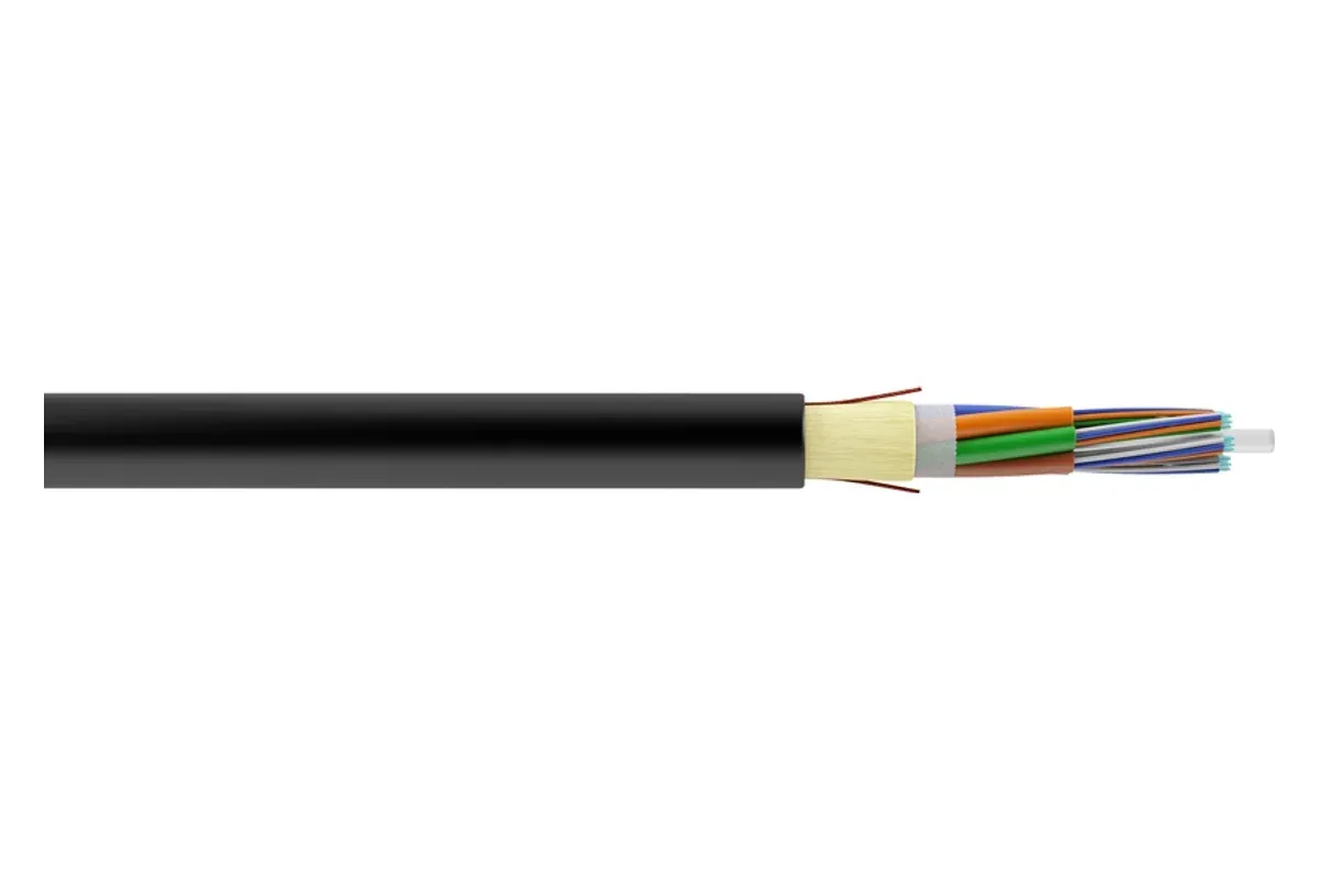
NetLast’s verified catalog includes a 12 Core ADSS Fiber Optic Cable. Use the current product page and datasheet to confirm fiber type, jacket, permitted span, mechanical ratings, diameter, drum length and installation hardware for the actual quotation.
What is Figure 8 fiber optic cable?
Figure 8 cable combines an optical cable with a messenger in one joined profile. The messenger is positioned above or beside the optical unit, so the cross-section resembles the number 8. In many widely used designs, the messenger is steel wire or stranded steel. Dielectric messenger variants also exist, so buyers should state the required material rather than relying on the product name.
The messenger provides a clear load-bearing element that can be clamped at poles. Installation teams may separate the web between the messenger and optical unit at attachment points, then secure the messenger with approved hardware while maintaining the cable’s minimum bend radius and handling limits.
Figure 8 cable is often considered for short or medium aerial distribution and access routes. That does not mean every Figure 8 cable is limited to the same span. Messenger size, cable weight, fiber construction, wind/ice load and safety factor determine the permitted application.
The main structural difference: where the load goes
The most important difference is the load path.
With ADSS, the round cable body carries the tensile load through its strength-member system. Dead-end and suspension hardware transfer that load from the cable into the pole structure. Hardware must grip the cable without crushing the optical core or overstressing the jacket.
With Figure 8 cable, the messenger is the primary load-bearing element. The optical unit is attached through the web. Hardware normally acts on the messenger section, but installers still need to protect the optical portion during separation, bending and access.
This difference affects:
- cable diameter and attachment hardware;
- pole-loading calculations;
- sag and tension tables;
- installation tools and crew familiarity;
- grounding/bonding work when the messenger is metallic;
- mid-span access and maintenance procedures;
- replacement strategy after storm or impact damage.
Electrical environment and power-line routes
ADSS is commonly considered near power infrastructure because it is all-dielectric. Metal-free ADSS designs avoid a conductive messenger, while common Figure 8 designs may use a steel messenger. The project engineer must still confirm electrical-field conditions, clearances, jacket selection, hardware, and safe work procedures.
However, “all-dielectric” is not the same as “install anywhere near electricity.” ADSS can be exposed to strong electrical fields, pollution and wet conditions that contribute to sheath tracking or dry-band arcing. The route owner should define the permitted pole zone and whether a standard PE or tracking-resistant jacket is required.
For Figure 8 cable with a metallic messenger, the project must address electrical clearance, grounding, bonding and induced-voltage risk under local utility rules. Do not install a metallic-messenger design in a power corridor simply because the optical fibers themselves are nonconductive.
When the route is on telecom-only poles, the electrical advantage of ADSS may be less important than span, hardware, installation method and cost. Start from the actual pole environment rather than the cable name.
Span, sag, wind and ice loading
Span length alone is not enough to select an aerial cable. A 100-meter span in a sheltered tropical route and the same span in a high-wind or ice-loaded region produce different mechanical requirements.
The RFQ should identify:
- ruling span or individual pole spans;
- maximum and minimum span;
- wind-speed or local loading case;
- ice thickness where applicable;
- installation temperature and operating temperature;
- required sag at installation and final condition;
- pole/attachment height and clearance requirement;
- expected safety factor;
- terrain, road crossings and river crossings;
- fiber count and cable weight constraints.
Ask the cable manufacturer for a sag-and-tension table or approved design for the exact model. Do not apply one supplier’s span rating to another supplier’s cable, even if both are labeled “100 m ADSS.”
Installation hardware and tools
Cable and hardware should be purchased as a matched system.
For ADSS, common hardware categories include dead-end assemblies, suspension units, armor rods, vibration-control accessories and pole brackets. The gripping length, cable diameter range and load rating must match the selected ADSS model.
For Figure 8, the hardware normally grips or terminates the messenger. The buyer may also need grounding/bonding accessories, brackets and cable-storage hardware. The messenger material and diameter should be included in the hardware schedule.
For both cable types, confirm:
- pulling method and maximum installation tension;
- minimum bend radius during pulling and after installation;
- sheave or roller diameter;
- permitted cable twist;
- pole attachment and clearance;
- closure location and slack-storage method;
- hardware quantity per pole and per route section.
A low cable price can be cancelled by incorrect or unavailable hardware, field rework or a second mobilization of the installation crew.
Which cable costs less?
Figure 8 cable is often described as the lower-cost choice because the messenger provides a straightforward support element and familiar hardware. ADSS may have a higher cable or hardware cost because its strength system and span design are integrated into the cable body.
That comparison is incomplete unless the buyer calculates total installed cost. Include:
- cable price per kilometer;
- dead-end and suspension hardware;
- grounding/bonding accessories;
- pole make-ready work;
- installation labor and crew training;
- pulling/tensioning equipment;
- maintenance and storm-repair method;
- drum length, waste and logistics;
- approval cost from the pole or utility owner.
The most economical option is the cable system that meets the route requirements with the lowest compliant installed and lifecycle cost—not automatically the lowest cable price.
Practical selection workflow
Step 1: identify pole ownership and route environment
Confirm whether the poles belong to a power utility, telecom operator, municipality or private campus. Obtain the owner’s cable and attachment rules.
Step 2: map every span and crossing
Mark normal spans, long spans, road crossings, corners, elevation changes and high-wind sections. Do not select from the average span only.
Step 3: define the electrical requirement
State whether metallic messenger is permitted, whether grounding is required and whether the ADSS jacket must be selected for a defined electrical field.
Step 4: request cable and hardware together
Send the cable diameter, mechanical design and load requirements to the hardware supplier—or request a matched cable-and-hardware proposal.
Step 5: compare compliant total cost
Compare both options only after each design meets pole loading, sag, clearance, mechanical and electrical requirements.
RFQ checklist: ADSS or Figure 8 aerial cable
| RFQ field | What to provide |
|---|---|
| Cable family | ADSS or Figure 8; request both options if undecided |
| Route ownership | Power utility, telecom pole, municipality or private route |
| Fiber | Fiber count, category and operator standard |
| Span data | Minimum, maximum, ruling span and special crossings |
| Loading | Wind, ice, temperature and local/NESC load case |
| Electrical environment | Pole zone, line voltage context, grounding rule and jacket requirement |
| Cable structure | Single/double jacket, loose tube/central tube and water blocking as required |
| Messenger | Material, size and grounding plan for Figure 8 |
| Mechanical values | Required tensile, crush, bend and sag/tension data |
| Hardware | Dead ends, suspension, brackets, armor rods and grounding accessories |
| Drum plan | Route lengths, drum length, tolerance and cutting schedule |
| Marking | Meter marking, cable legend, customer name and batch identification |
| Documents | Datasheet, construction drawing, test report and sag/tension table |
| Delivery | Quantity, batches, destination and packing/shipping marks |
Sending a route drawing and pole schedule is more useful than asking only for “24-core ADSS price” or “Figure 8 cable price.”
Production and quality checks for aerial cable orders
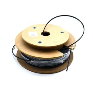
Real production images help buyers understand whether cable handling, drum winding and manufacturing equipment are relevant to the order. They should be used together with traceable documents—not as a substitute for them.
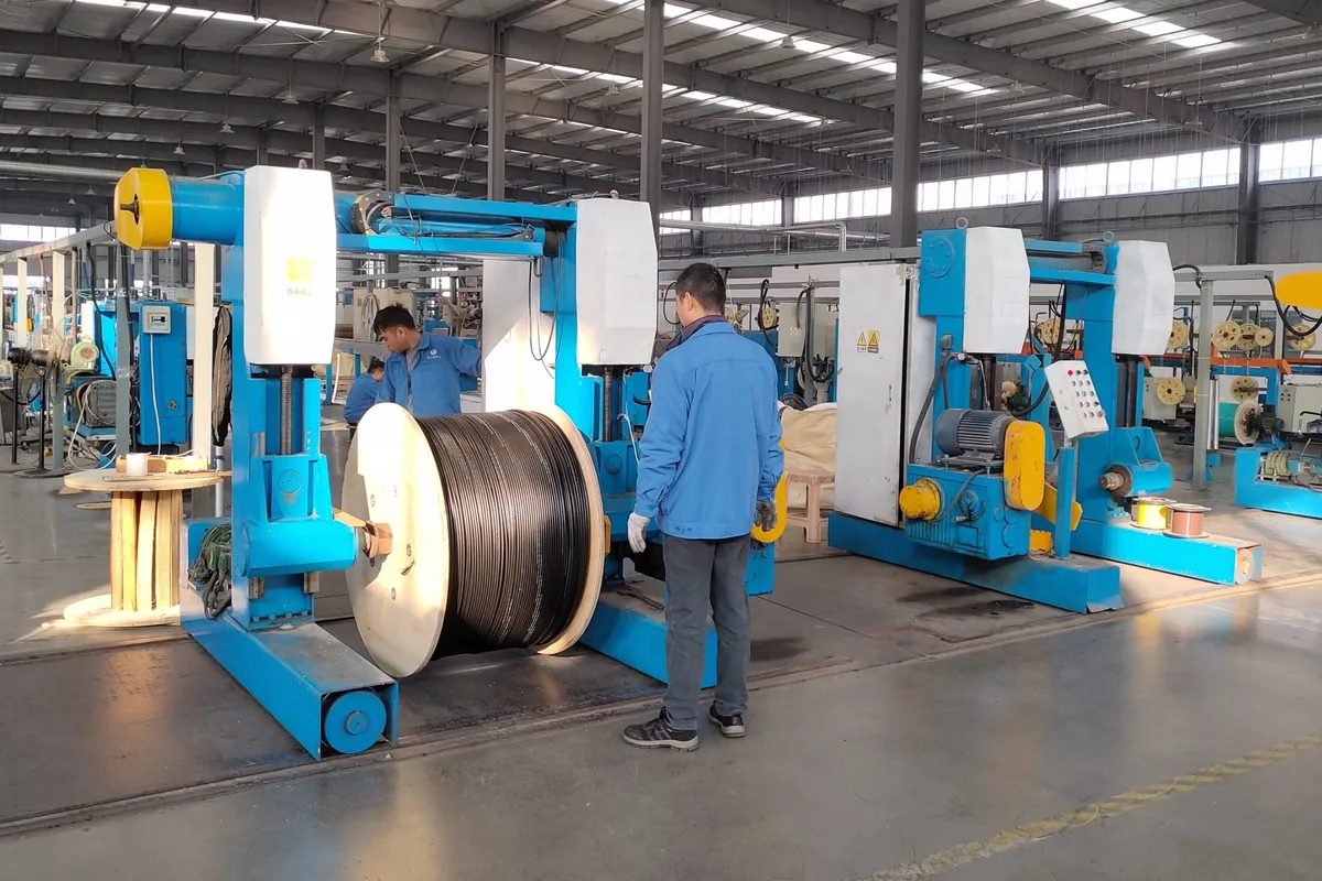
Before mass production or shipment, consider confirming:
- approved construction drawing and bill of materials;
- fiber count, tube color sequence and fiber category;
- cable diameter, weight and jacket thickness according to the agreed specification;
- strength-member or messenger construction;
- cable marking and sequential meter marks;
- optical attenuation test method and report format;
- mechanical test requirements and sampling plan;
- drum length, end sealing, labels and export protection;
- batch numbers and inspection-photo format.
For ADSS, the sag-and-tension design and compatible hardware schedule are particularly important. For Figure 8, confirm messenger material, dimensions and any grounding accessories. Record acceptance criteria in the purchase order before production.
Common purchasing mistakes
Treating “all-dielectric” as the complete ADSS specification
ADSS still needs a defined span, load case, jacket, diameter, tensile design and hardware.
Comparing different load conditions
A supplier’s 200 m span claim under light loading cannot be compared with another cable rated under heavy wind or ice conditions.
Ignoring the messenger material
Figure 8 cable may use metallic or dielectric messenger designs. State which is required and plan grounding where applicable.
Ordering cable before hardware
If compatible dead ends or suspension clamps are not available, the cable may sit on site while the installer searches for a solution.
Using average span instead of worst-case span
The longest crossing, corner pole or exposed hill section can control the cable design.
FAQs
Is ADSS cable always suitable near power lines?
No. ADSS avoids a conductive messenger, but the utility must approve the attachment zone, clearances, electrical-field conditions, jacket design, hardware and work procedure for the specific route.
Does Figure 8 cable always have a steel messenger?
Many common Figure 8 fiber cables use steel wire or stranded steel, but dielectric messenger versions also exist. Confirm the messenger material on the datasheet and RFQ.
Can ADSS and Figure 8 use the same clamps?
Usually not. ADSS hardware grips the cable body and must match its diameter and tensile design. Figure 8 hardware normally acts on the messenger. Use hardware approved for the exact cable.
Which cable is better for long spans?
Neither cable family is automatically better for every long span. Compare manufacturer-approved designs under the same wind, ice, sag, temperature and safety-factor conditions.
What should buyers send for an accurate quotation?
Send route ownership, pole schedule, spans, loading conditions, fiber count/type, electrical environment, jacket requirement, hardware list, drum plan, quantity, destination and required test documents.
Need an aerial cable recommendation for your route?
Send NetLast your pole route or drawing, minimum and maximum spans, wind/ice or local load case, electrical environment, fiber count and type, cable structure, jacket requirement, hardware list, drum-length plan, quantity, delivery country and required test documents. We can review the inputs and prepare an ADSS cable quotation or help you compare it with a messenger-supported Figure 8 option.
Send Your Aerial Cable Requirements
References
Aerial routes near trees may also need rodent protection. See how metallic and all-dielectric anti-rodent cable designs differ before approving the cable BOM.