MPO Polarity Methods A, B and C Explained with Fiber Maps
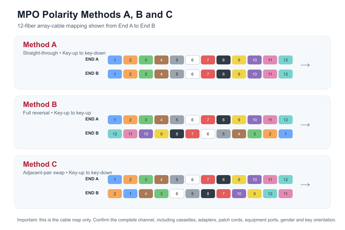
MPO polarity defines how fiber positions connect across a multi-fiber channel so that every transmitter reaches the intended receiver. For the common 12-fiber array-cable examples used in this guide, Method A is straight-through, Method B reverses the complete fiber order, and Method C swaps adjacent fiber pairs.
That short answer is useful, but it is not enough for purchasing. Polarity is an end-to-end channel decision, not just a label printed on one trunk cable. The final result depends on the trunk, adapters, cassettes or modules, patch cords, equipment interfaces, connector pinning and key orientation. A cable can match its own drawing and still be wrong for the installed channel.
This guide is written for data-center integrators, cabling contractors, distributors and procurement teams that need a clear fiber map and a practical RFQ checklist before ordering MPO/MTP assemblies.
Quick comparison: MPO Methods A, B and C
| Method | 12-fiber array-cable map | Typical key orientation | Main procurement point |
|---|---|---|---|
| Method A | 1→1, 2→2 … 12→12 | Key-up to key-down | The trunk is straight-through; the complete channel still needs the correct cassette and patch-cord logic. |
| Method B | 1→12, 2→11 … 12→1 | Key-up to key-up | The array is fully reversed; often considered for direct MPO and parallel-optics paths, subject to the equipment map. |
| Method C | 1→2, 2→1; 3→4, 4→3 … | Key-up to key-down | Adjacent pairs are swapped; confirm that the cassette or breakout architecture was designed for this method. |
The table describes a common 12-fiber array-cable map. It does not replace the complete channel drawing. Different fiber counts, multi-row ferrules and vendor-specific systems can use different maps or terminology, so the supplier and integrator should approve the exact diagram before production.
What does MPO polarity mean?
In a duplex optical link, the transmit path at one end must arrive at the receive path at the other end. With LC duplex cabling, technicians can often follow one pair at a time. An MPO connector places multiple fibers in one ferrule, so several Tx and Rx paths can be affected by one mapping decision.
ANSI/TIA-568.3-E is the current TIA optical-fiber cabling component standard announced in 2022. It covers optical cabling components and connectivity arrangements. Methods A, B, and C are the standard polarity approaches used to create the required end-to-end Tx/Rx relationship in MPO channels.
Three ideas should be kept separate:
- Fiber map: which numbered position at End A connects to which position at End B.
- Key orientation: whether the connector key is oriented key-up or key-down at each end.
- Gender or pinning: whether the MPO connector is pinned or unpinned, often called male or female.
Changing one of these does not automatically change the other two. A purchase order that states only “MPO-12 cable” leaves important channel information unresolved.
MPO versus MTP: is the polarity logic different?
MPO is the generic multi-fiber push-on connector format. MTP® is a proprietary MPO connector brand that uses the standardized MPO interface. MTP assemblies remain part of the MPO connector family and still require a defined fiber map, pinning, key orientation, and channel design.
For procurement, do not treat “MTP” as a polarity method. An MPO or MTP assembly can still require a defined fiber count, connector pinning, key orientation, fiber type, end-face geometry, length, jacket and fiber map. Use the exact connector brand only when the project specification requires it.
How to read a 12-fiber MPO map
Start with the numbered fiber positions at End A, normally shown as 1 through 12. The approved drawing should then show which numbered position appears at End B. The diagram at the top of this article uses three simple sequences:
- Method A End B: 1, 2, 3, 4, 5, 6, 7, 8, 9, 10, 11, 12;
- Method B End B: 12, 11, 10, 9, 8, 7, 6, 5, 4, 3, 2, 1;
- Method C End B: 2, 1, 4, 3, 6, 5, 8, 7, 10, 9, 12, 11.
Always check the drawing’s viewing direction. “Looking into the ferrule” and “looking from the cable side” can reverse the apparent order. A reliable supplier drawing should label End A, End B, key position, position 1, pinning and the viewing direction.
Method A: straight-through array cable
In a Type A 12-fiber array cable, position 1 connects to position 1, position 2 connects to position 2, and the pattern continues through position 12. The connector keys are normally opposite—key-up at one end and key-down at the other.
The straight-through trunk does not by itself complete every Tx/Rx crossover required by a duplex channel. Method A channel designs use the specified combination of modules, adapters and patch cords to create the correct end-to-end relationship. That is why a contractor should not substitute a patch cord simply because the connector and fiber type look the same.
When Method A may fit
- structured cabling designs where the trunk remains straight-through;
- cassette-based paths with an approved Method A component schedule;
- projects that already maintain Method A documentation and spare inventory.
The phrase “may fit” is deliberate. The final choice depends on the transceiver interface and every component in the channel.
Method B: full fiber-order reversal
In a Type B 12-fiber array cable, position 1 maps to 12, position 2 maps to 11, and the sequence continues in reverse. Both connector keys are normally oriented the same way, commonly described as key-up to key-up.
Method B is frequently discussed for direct MPO and parallel-optics applications because the full reversal can align opposite transmit and receive lane groups. It is also used within structured systems that have matching Method B cassettes or modules. However, “parallel optics means Method B” should never replace a transceiver and channel review. MPO-8, MPO-12, MPO-16 and other interfaces do not all use the same active positions or ferrule layout.
Questions to answer before ordering Method B
- Which transceiver standard and port interface will be connected?
- How many fiber positions are present, and which positions are active?
- Is the path direct MPO-to-MPO, or does it include cassettes and LC patching?
- What pinning is required at the equipment and adapter interfaces?
- Does the approved manufacturer drawing show the same End A/End B orientation?
Method C: adjacent-pair swap
Method C swaps adjacent fiber pairs. On a 12-fiber cable, positions 1 and 2 exchange, positions 3 and 4 exchange, and the same pairwise pattern continues through positions 11 and 12. The connectors are normally key-up to key-down.
This method can support channel designs that maintain duplex pairs through a breakout or cassette architecture. It should not be selected only because the project uses duplex LC ports. The cassettes, port numbering, patch cords and future migration plan must be designed around the same pairwise map.
Method C can create operational difficulty when the installed team expects Method A or Method B inventory. If it is required, label the trunks and panels clearly and include the map in both the installation package and the test report.
Why a correct MPO cable can create a failed link
A factory can build a trunk exactly according to its approved cable map, yet the installed link can still fail if another component uses a different polarity assumption. Common causes include:
- a Method A trunk connected to cassettes designed for a Method B channel;
- patch cords with an unexpected duplex orientation;
- one replacement cassette with different internal mapping;
- pinned and unpinned connectors that cannot mate correctly through the selected adapter;
- an MPO-12 cable used with equipment that expects a different active-fiber arrangement;
- End A and End B labels interpreted from opposite viewing directions;
- an undocumented field polarity change on a configurable connector.
The solution is to approve the channel, not only the part number. A useful submittal shows every connection from equipment port to equipment port and includes the numbered fiber path.
Key orientation is not the same as connector gender
The MPO key controls rotational orientation. Connector pinning controls mechanical alignment between the two ferrules. A pinned connector must mate with a compatible unpinned connector through the correct adapter arrangement. Two connectors with the correct polarity map can still be mechanically incompatible if the pinning plan is wrong.
Use both terms in the RFQ:
- End A: pinned or unpinned, key orientation, fiber position 1;
- End B: pinned or unpinned, key orientation, fiber position 1;
- adapter: aligned or opposed key orientation as required by the approved system;
- equipment port: interface and pinning confirmed from the equipment datasheet.
Do not assume that “female cable” is always correct for every transceiver or panel. Confirm the equipment port and every mated pair.
Do not extend a 12-fiber map blindly to MPO-8, MPO-16 or MPO-24
The illustrations in this article show a single row of 12 positions. Other MPO interfaces can use different numbers of active fibers, empty positions or multi-row ferrules. Application lane assignments also change between duplex breakout, SR4, SR8, DR4, PSM and vendor-specific systems.
For any non-identical interface, request:
- a connector-face drawing;
- active and unused fiber positions;
- End A-to-End B fiber map;
- Tx/Rx lane assignment from the equipment datasheet;
- breakout or cassette port mapping;
- a polarity test result for the supplied assembly.
A label such as “Method B” is helpful, but the numbered map is the final engineering reference.
How should MPO polarity be tested?
Polarity testing verifies continuity and the numbered position map. Some multi-fiber test systems can verify Methods A, B, and C while testing multiple MPO fibers. The exact tester and procedure can vary, but the acceptance document should show lane-level results rather than only a simple “pass” label.
A practical test sequence is:
- Confirm the approved cable drawing, connector pinning and key orientation.
- Inspect and clean both MPO end faces using approved tools.
- Connect the cable to a polarity or multi-fiber continuity tester.
- Verify every numbered fiber from End A to End B.
- Record missing, duplicated, reversed or unexpected positions.
- Complete insertion-loss testing under the agreed method when required.
- Attach the cable serial or batch reference to the report.
Visual inspection alone cannot confirm the internal fiber map. A clean ferrule can still belong to the wrong polarity type.
Example NetLast MPO trunk cable
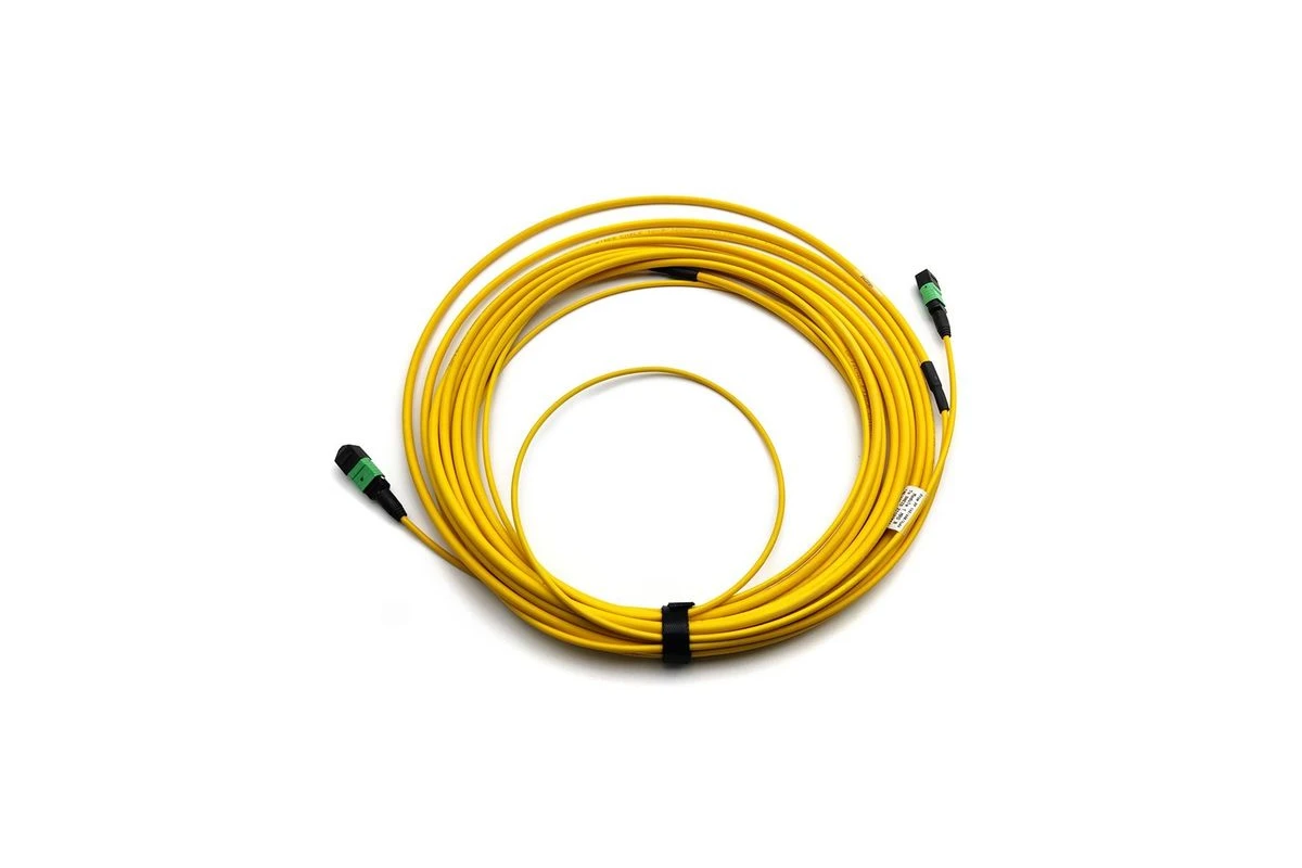
NetLast’s current MPO-MPO Female Trunk Cable page presents a specific 12-fiber Type A female-to-female OS2 trunk configuration. That page is an example of one defined assembly—not evidence that every polarity, fiber count, connector brand or pinning option is available.
For a quotation, send the complete channel requirement. NetLast can then confirm the requested configuration, available documentation and production details instead of assuming that an existing product-page example fits a different project.
MPO/MTP RFQ checklist
| RFQ field | Information to provide |
|---|---|
| Application | Data-center trunk, direct parallel optics, cassette link, breakout or equipment connection |
| Equipment | Transceiver or switch model and the relevant interface datasheet |
| Connector | MPO or specified MTP® brand connector at each end |
| Fiber count | Exact connector position count and active-fiber count |
| Fiber type | Project-specified single-mode or multimode category |
| Polarity | Method A, B or C plus the approved numbered fiber map |
| Pinning | Pinned or unpinned at End A and End B |
| Key orientation | Key-up/key-down relationship and adapter type |
| End face | Geometry and polish required by the equipment and project specification |
| Cable | Length, outer diameter, jacket rating, color and pulling-eye requirement |
| Loss requirement | Acceptance limit and test method from the project specification |
| Documentation | Fiber map, polarity result, insertion-loss report, end-face record and labels |
| Packaging | Individual label, serial/batch number, bag or reel and shipment marks |
| Quantity and delivery | Required quantity, batches, destination and requested delivery schedule |
Attach the channel drawing and equipment datasheets whenever possible. That information is more useful than asking only for “MPO Type B cable price.”
Production and documentation checks
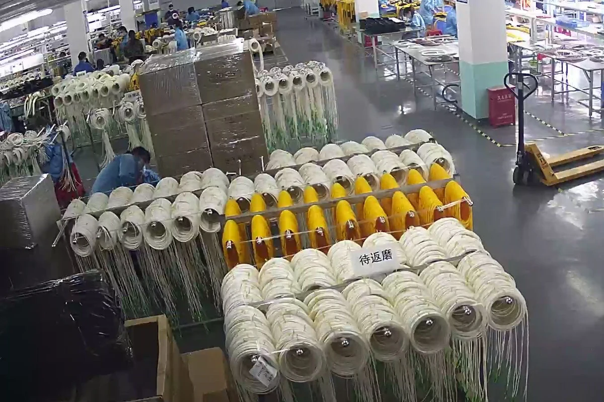
Production images can help buyers understand the assembly environment, but they should be supported by traceable order documents. Before shipment, consider confirming:
- approved cable construction and End A/End B drawing;
- fiber count, fiber type and color sequence;
- connector brand when a brand is contractually required;
- pinning and key orientation at both ends;
- polarity map for every supplied cable family;
- end-face inspection and cleaning procedure;
- test method, acceptance criteria and report format;
- serial number, batch number and label wording;
- length, tolerance, pulling eye and protective packing.
Freeze these requirements before mass production. Changing polarity or pinning after the assemblies have been built can create rework, retesting and project delay.
Common MPO polarity purchasing mistakes
Ordering by cable color
Jacket or connector color can support identification, but it does not prove the polarity map, pinning or application. Use the drawing and test report.
Using “male” or “female” as the polarity specification
Gender describes guide pins. It does not define whether the fiber sequence is Method A, B or C.
Copying a previous part number without checking the channel
A new transceiver, cassette or panel can change the required map even when the cable length and connector shell look identical.
Approving only the trunk drawing
The trunk is one part of the channel. Include cassettes, adapters, duplex patch cords and equipment ports in the same review.
Skipping polarity testing because insertion loss passed
Insertion loss and polarity answer different questions. A low-loss path can still connect the wrong numbered positions.
FAQs
What is the difference between MPO Method A and Method B?
For a common 12-fiber array cable, Method A is straight-through from position 1 to 1 through 12 to 12. Method B reverses the order from 1 to 12, 2 to 11 and so on. The complete channel also requires matching adapters, cassettes and patch cords.
Is MTP polarity different from MPO polarity?
No separate polarity family is implied by the MTP name. MTP® is a proprietary MPO connector brand. The assembly still needs a defined fiber map, pinning, key orientation, and channel design.
Which MPO polarity is best for parallel optics?
Method B is often used in direct parallel-optics architectures, but it is not universally correct for every interface. Confirm the transceiver standard, active fiber positions, connector type and complete channel drawing.
Can I identify MPO polarity by looking at the connector?
You may see key orientation and pinning, but you cannot reliably confirm the internal fiber map by visual inspection alone. Check the approved drawing and perform a polarity test.
What should be included in an MPO trunk cable quotation request?
Provide the application, equipment interface, fiber count and type, polarity map, pinning, key orientation, end-face requirement, length, jacket, test requirements, documentation, quantity and destination.
Need help confirming an MPO/MTP channel?
Send NetLast your transceiver or equipment model, fiber count, polarity method, numbered fiber map, connector pinning, key orientation, fiber type, cable length, jacket requirement, cassette or breakout layout, test-document requirements, quantity and delivery destination. We can review the requested assembly details and prepare a quotation based on the confirmed configuration.
Send Your MPO/MTP Cabling Requirements