MPO/MTP Cable Testing Checklist: IL, RL, Polarity and End-Face
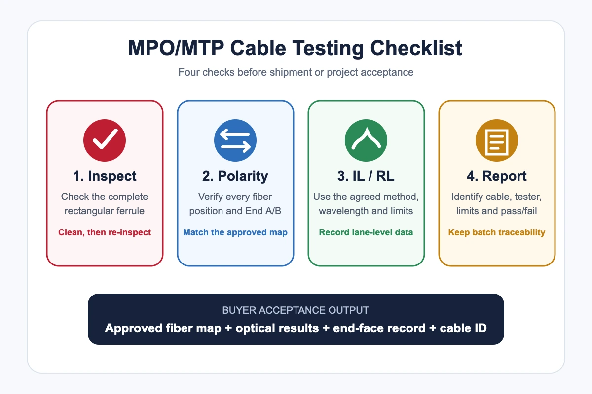
An MPO/MTP cable should not be accepted on insertion loss alone. Buyers and integrators should confirm four items: end-face condition, fiber-position mapping, optical loss and traceable test documentation. The pass limits and test method must come from the approved project specification, not from a generic online table.
This concise checklist is for factory acceptance, incoming inspection and pre-installation review of MPO trunks and patch cords.
Quick MPO/MTP testing checklist
| Check | What it confirms | Buyer action |
|---|---|---|
| End-face inspection | Debris, scratches and visible defects on the ferrule contact area | Require inspect-clean-reinspect records when specified |
| Polarity and continuity | Each numbered fiber reaches the intended position at the opposite end | Approve the End A-to-End B fiber map before production |
| Insertion loss (IL) | Optical power lost through the tested assembly or link | State wavelength, reference method and acceptance limit |
| Return loss (RL) | Reflected optical power at interfaces | State whether RL is required and the applicable limit |
| Test report | Which cable, fibers, settings and limits produced the result | Match the report to cable or batch identification |
1. Inspect and clean the complete MPO end face
IEC 61300-3-35:2022 covers visual inspection of fiber-optic connector end faces. For a rectangular ferrule, inspection includes the whole contact surface, not only a quick view of one fiber. The standard also makes an important distinction: visual inspection supports cleanliness control but does not replace optical performance measurements.
Use the sequence inspect → clean if needed → re-inspect → connect. Check both cable ends, adapters or equipment ports, and the test cords. A dirty test cord can spread contamination and distort several lane results at once.
Do not treat an end-face photo as an IL/RL report. It answers a different question.
2. Verify polarity and every fiber position
Polarity testing confirms that each fiber at End A reaches the intended position at End B. This is essential because a low-loss cable can still fail in service when its mapping is wrong.
Before testing, the approved document should identify:
- fiber count and active positions;
- Method A, B or C, plus the numbered map;
- End A and End B viewing direction;
- key orientation and pinned or unpinned connector ends;
- breakout branch or cassette port numbering, when used.
Some multi-fiber test systems scan MPO fibers and report loss and polarity together. The equipment may differ, but buyers should still request lane-level results rather than a single unchecked “polarity passed” note.
3. Measure insertion loss with an agreed method
Insertion loss is the optical power lost between the input and output of the tested assembly or channel. A useful report identifies the wavelength, test direction, reference method, test-cord arrangement and limit applied to every lane.
Do not copy an IL limit from another project. The acceptable value depends on the assembly, connector grade, number of mated pairs and the system loss budget. Factory testing of one cable also differs from field certification of a complete link containing adapters, cassettes and additional patch cords.
If several lanes rise together, first check cleanliness, test cords and referencing. If one lane is abnormal, investigate the specific fiber position, connector or branch.
4. Confirm whether return loss is required
Return loss describes reflected optical power. A higher numerical RL value generally represents less reflection, but the required value and measurement method must come from the project or product specification.
Some buyers require IL and RL for every finished cable; others use different acceptance plans for factory assemblies and installed links. State the requirement before quotation so the supplier can confirm equipment, wavelengths, limits and report format.
What should an MPO/MTP test report show?
| Report field | Why it matters |
|---|---|
| Order, cable or batch ID | Connects the result to the delivered item |
| Connector and fiber configuration | Confirms the tested assembly matches the order |
| Fiber map and polarity result | Shows position-by-position continuity |
| IL/RL by lane | Reveals outliers hidden by an average |
| Wavelength and test direction | Makes results interpretable and repeatable |
| Reference method and test equipment | Provides measurement context |
| Acceptance limit and pass/fail | Shows which approved requirement was applied |
| Date and operator or station | Supports production traceability |
Product and production context
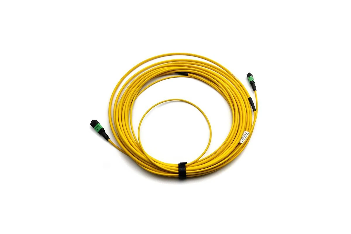
NetLast’s current MPO-MPO Female Trunk Cable page shows one specific 12-fiber Type A OS2 female-to-female configuration. It is an ordering example, not proof that every connector, polarity or test option is available. Send the complete assembly and acceptance requirements for confirmation.
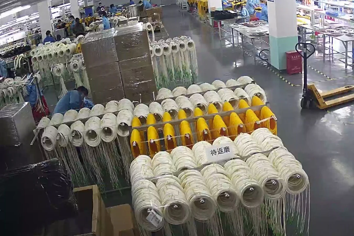
For project orders, agree on inspection records, optical tests, labels and packaging before production. A workshop photo can support supplier transparency, but the signed specification and traceable results are the evidence used for acceptance.
MPO/MTP cable RFQ test requirements
- assembly type, fiber count, fiber type and length;
- connector brand if mandatory, end-face geometry and pinning;
- polarity method and numbered fiber map;
- IL and RL wavelengths, directions and limits;
- end-face inspection criteria and image requirement;
- report format, cable ID and batch traceability;
- quantity, sample approval and delivery destination.
FAQs
Is insertion loss testing enough for an MPO cable?
No. IL does not confirm a clean end face or correct Tx/Rx mapping. Add polarity verification and the inspection requirements defined by the project.
Should every fiber position appear in the report?
For a multi-fiber assembly, lane-level results make it easier to find a wrong map or one abnormal channel. Define the required report format before ordering.
Is 3D interferometer testing the same as end-face inspection?
No. Visual inspection checks contamination and visible defects. Interferometry measures ferrule and fiber geometry. A project may request one or both, plus IL/RL testing.
Can factory results replace field acceptance testing?
Not always. Factory data applies to the supplied assembly; field testing can verify the complete installed link after handling, routing and mating.
Send your MPO/MTP test requirements
Need test records with your MPO/MTP cable quotation?
Send NetLast the fiber count, polarity map, connector ends, IL/RL limits, inspection criteria, report format and quantity. We will confirm the requested configuration and available documentation before quotation.