Fiber Optic Fast Connector Installation: 7 Checks That Prevent High Loss
A fast connector saves time only when the first termination works. The connector may remove the need for fusion splicing, epoxy and field polishing, but it cannot correct a dirty fiber, a poor cleave or the wrong cable dimensions.
If a new SC/APC termination shows high loss, do not immediately blame the connector. Slow down and check the preparation sequence. The following seven checks are short enough to use at a distribution box or subscriber outlet.
Before opening the connector
Confirm four things before stripping the cable:
- the connector is designed for the actual drop cable, cord or coated fiber;
- the connector interface and polish match the equipment and adapter;
- the strip and cleave lengths come from the instructions for that exact connector;
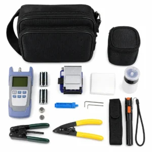
- the stripper, cleaver, cleaning materials and test cords are clean and in good condition.
One model’s preparation dimensions should not be reused for another model simply because both connectors look like SC connectors.
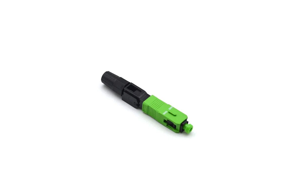
For example, the NetLast NL-SCAPC/600A product page identifies a 60 mm, simplex SC/APC field-assembly connector for G.657.A1 single-mode fiber. A buyer still needs to confirm the cable construction and installation requirements for the order rather than selecting by housing colour alone.
Seven installation checks that matter
1. Strip to the specified length
Too much exposed glass leaves poor strain relief. Too little may stop the fiber before it reaches the internal alignment point. Use the connector’s own length guide or jig, not a remembered number from a different product.
2. Clean the bare fiber and leave it alone
After stripping, clean the bare fiber with the material recommended for fiber preparation. Do not touch the glass or place it on the work surface. If the fiber is handled again, clean it again before cleaving.
3. Check the cleave, not just the cleaver
A worn blade, incorrect fiber position or damaged coating can produce a poor end. Confirm the cleave length and examine the result using the method required by the connector supplier. If the cleave is doubtful, start again; forcing it into the connector rarely improves it.
4. Insert the fiber without forcing it
Keep the prepared fiber aligned with the entry channel. Follow the model-specific indicator, stop or fiber-bow instruction that confirms full insertion. Resistance at the wrong point can mean the fiber has met an obstruction or the preparation length is incorrect.
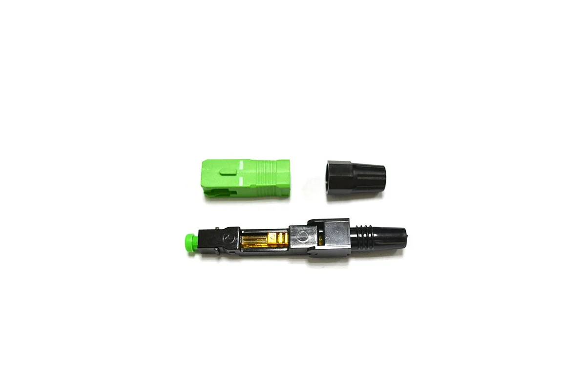
5. Lock the splice before relaxing the fiber
Activate the wedge, cam or locking mechanism in the sequence shown by the manufacturer. Then secure the cable strain relief. The cable jacket or strength member should take handling load; the bare glass should not.
6. Inspect the connector end face
The ferrule may be factory polished, but the exposed end face can still collect dust from a cap, hand or adapter. Inspect before mating. If inspection shows contamination, clean with a suitable fiber-cleaning method and inspect again.
7. Test the completed termination
A visual fault locator is useful for continuity checks and obvious faults, but it does not provide a quantitative insertion-loss result. Test the finished connection using the method and limits stated in the project specification. Record the cable or outlet ID when traceability is required.
Quick checks when the result is poor
| Symptom | First items to check |
|---|---|
| Loss is high but stable | Cleave quality, preparation length, full fiber insertion and end-face cleanliness |
| Reading changes when the cable moves | Cable fit, locking sequence and strain relief |
| VFL light passes but the power test fails | Internal alignment, cleave condition, reflection and test-reference setup |
| Several terminations fail in a row | Stop and check the cleaver, stripper, cleaning process, preparation dimensions and connector lot |
These are starting points, not automatic diagnoses. The test method and acceptance limit should come from the project documents.
When should you remake the termination?
Remake it when the cleave is damaged, the preparation length is wrong or the fiber was contaminated before insertion. Replace the connector if the ferrule or external end face is damaged. Do not repeatedly open and close a mechanical connector unless the manufacturer specifically describes it as re-enterable.
For repeated failures, keep one failed sample, record the lot number and compare the technician’s process with the supplier’s assembly instructions. That evidence is much more useful than a message saying only “high loss.”
What buyers should put in the RFQ
- connector interface and polish, such as SC/APC;
- fiber type and exact cable dimensions;
- connector model or required overall length;
- required IL/RL limits and test method;
- sample-approval and batch-report requirements;
- individual packaging, label and quantity;
- matching tools or assembly guide if required.
Need a fast connector matched to your drop cable?
Send NetLast a cable photo or drawing, fiber type, cable dimensions, connector interface, quantity and test requirements. We can confirm the requested configuration and available documentation before quotation.
FAQs
Does a fast connector need a fusion splicer?
A pre-polished mechanical field connector is designed for assembly without fusion splicing. It still requires correct stripping, cleaning, cleaving, locking and testing.
Can one strip-and-cleave length be used for every SC fast connector?
No. Internal structures and length guides differ. Use the instructions supplied for the exact model being installed.
Why can a connector look fine but still fail the loss test?
The housing can be assembled while the internal fiber is short, poorly cleaved, contaminated or not fully locked. Visual appearance alone does not verify optical performance.